
📄 Network Documentation – Final Project
🌐 Objective
Create a network divided into three different subnets for clients, administrators, and servers, connected via a switch and a router, using VLANs for segmentation and Router-on-a-Stick for inter-VLAN communication.
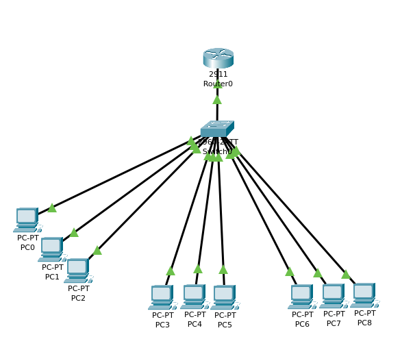
🧩 Network Topology
1️⃣ Central Switch
1️⃣ Router 2911
9️⃣ PCs:
👨💻 3 Clients (PC0 – PC2)
🛠️ 3 Administrators (PC3 – PC5)
💾 3 Servers (PC6 – PC8)
🧠 VLAN and Subnet Division
| Network | VLAN | Subnet | Gateway |
|---|---|---|---|
| 🧑💻 Clients | 10 | 192.168.1.0/24 | 192.168.1.1 |
| 🛠️ Admins | 20 | 192.168.2.0/24 | 192.168.2.1 |
| 💾 Servers | 30 | 192.168.3.0/24 | 192.168.3.1 |
🔌 Switch Port Assignment
fa0/1 to fa0/3: VLAN 10 (Clients)
fa0/4 to fa0/6: VLAN 20 (Admins)
fa0/7 to fa0/9: VLAN 30 (Servers)
fa0/10: Connection to router (trunk)
🔧 Switch Configuration
vlan 10
 name CLIENTS
vlan 20
 name ADMINS
vlan 30
 name SERVERS

interface range fa0/1 - 3
 switchport mode access
 switchport access vlan 10

interface range fa0/4 - 6
 switchport mode access
 switchport access vlan 20

interface range fa0/7 - 9
 switchport mode access
 switchport access vlan 30

interface fa0/10
 switchport mode trunk
 no shutdown
🚦 Router Configuration (Router-on-a-Stick)
interface g0/0.10
 encapsulation dot1Q 10
 ip address 192.168.1.1 255.255.255.0

interface g0/0.20
 encapsulation dot1Q 20
 ip address 192.168.2.1 255.255.255.0

interface g0/0.30
 encapsulation dot1Q 30
 ip address 192.168.3.1 255.255.255.0

interface g0/0
 no shutdown
💻 PC IP Configuration
| PC | IP Address | Subnet Mask | Gateway | VLAN |
|---|---|---|---|---|
| PC0 | 192.168.1.10 | 255.255.255.0 | 192.168.1.1 | 10 |
| PC1 | 192.168.1.11 | 255.255.255.0 | 192.168.1.1 | 10 |
| PC2 | 192.168.1.12 | 255.255.255.0 | 192.168.1.1 | 10 |
| PC3 | 192.168.2.10 | 255.255.255.0 | 192.168.2.1 | 20 |
| PC4 | 192.168.2.11 | 255.255.255.0 | 192.168.2.1 | 20 |
| PC5 | 192.168.2.12 | 255.255.255.0 | 192.168.2.1 | 20 |
| PC6 | 192.168.3.10 | 255.255.255.0 | 192.168.3.1 | 30 |
| PC7 | 192.168.3.11 | 255.255.255.0 | 192.168.3.1 | 30 |
| PC8 | 192.168.3.12 | 255.255.255.0 | 192.168.3.1 | 30 |
🔁 Connectivity Tests ✔️ Ping between PCs in the same VLAN
✔️ Ping between different VLANs (clients, admins, servers)
✔️ Ping to the gateways
Everything worked correctly in both real-time and simulation (after ARP resolution).
✅ Conclusion
This network is fully functional and securely segmented using VLANs. Thanks to the Router-on-a-Stick configuration, devices across different subnets can communicate properly. It’s a scalable structure suitable for adding services like:
DHCP
DNS
ACLs
Web Servers